STUDENT-LED AEROSPACE ENGINEERING PROJECT
ARES ReFlight
A modular fixed-wing UAV ecosystem for post-disaster reconnaissance, mapping, and engineering research.
Custom ground-control software. Modular air vehicle. Telemetry architecture. A planned automated antenna-tracking ground station.
01 · THE MISSION
Timely aerial information should not depend on expensive, inaccessible systems.
During disasters, access to current aerial information can be limited by cost, damaged infrastructure, and deployment complexity.
ARES explores how a low-cost, repairable, modular fixed-wing system could support rapid mapping and situational awareness—while remaining accessible for engineering research and education.
02 · SYSTEM ARCHITECTURE
One ecosystem. Four engineered layers.
ARES ReFlight is being developed as a connected stack. Select a module to inspect its purpose, function, and verified development state.
ANALYSIS
ARES-01 Software
The software foundation for telemetry, mission planning, simulation control, replay, and engineering analysis.
- PRIMARY FUNCTIONS
- MAVLink telemetrySITL integrationReplay and diagnostics
- CURRENT STAGE
- Initial stable desktop release — v1.3.0
03 · SOFTWARE FOUNDATION
ARES-01
A Windows-native research environment for designing, monitoring, controlling, replaying, analyzing, and documenting fixed-wing UAV simulation.
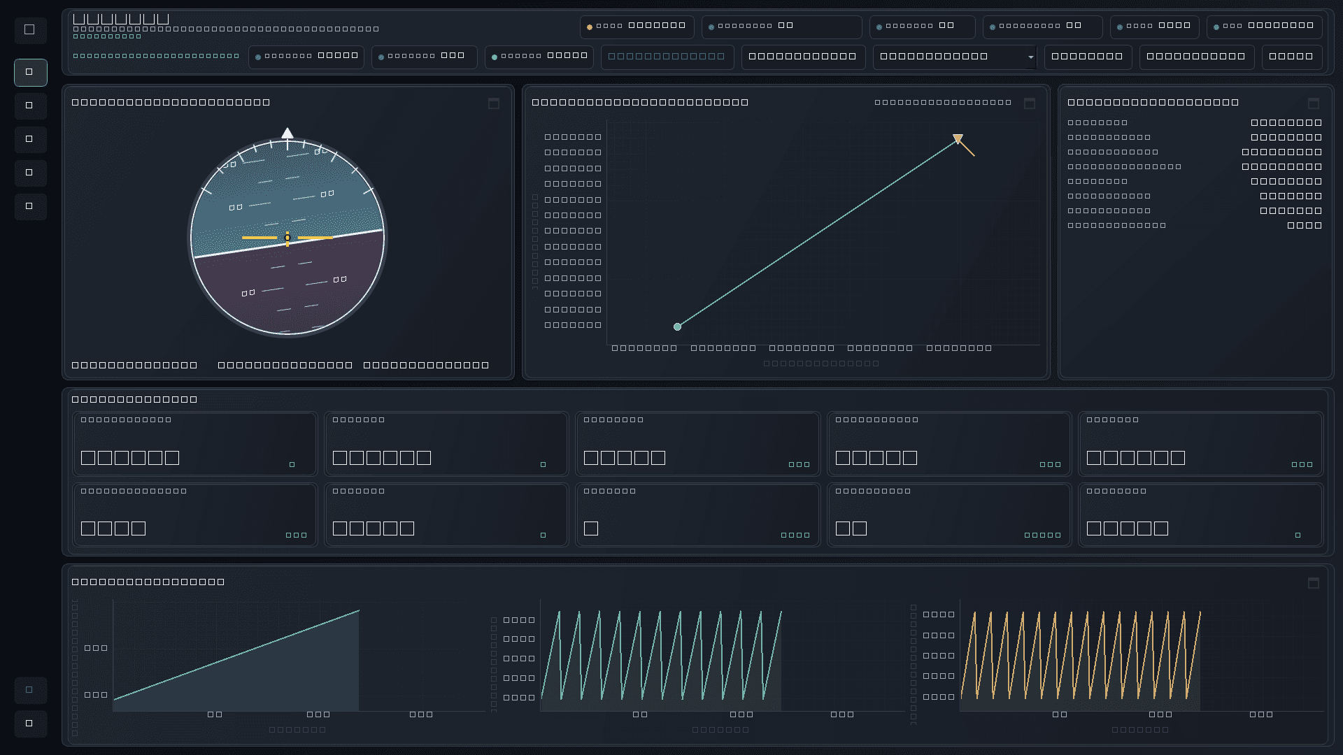
CAPABILITIES / VERIFIED SOFTWARE
Commands are restricted to verified local ArduPlane SITL and require explicit operator enablement.
Hardware flight integration has not yet been validated.04 · AIR VEHICLE
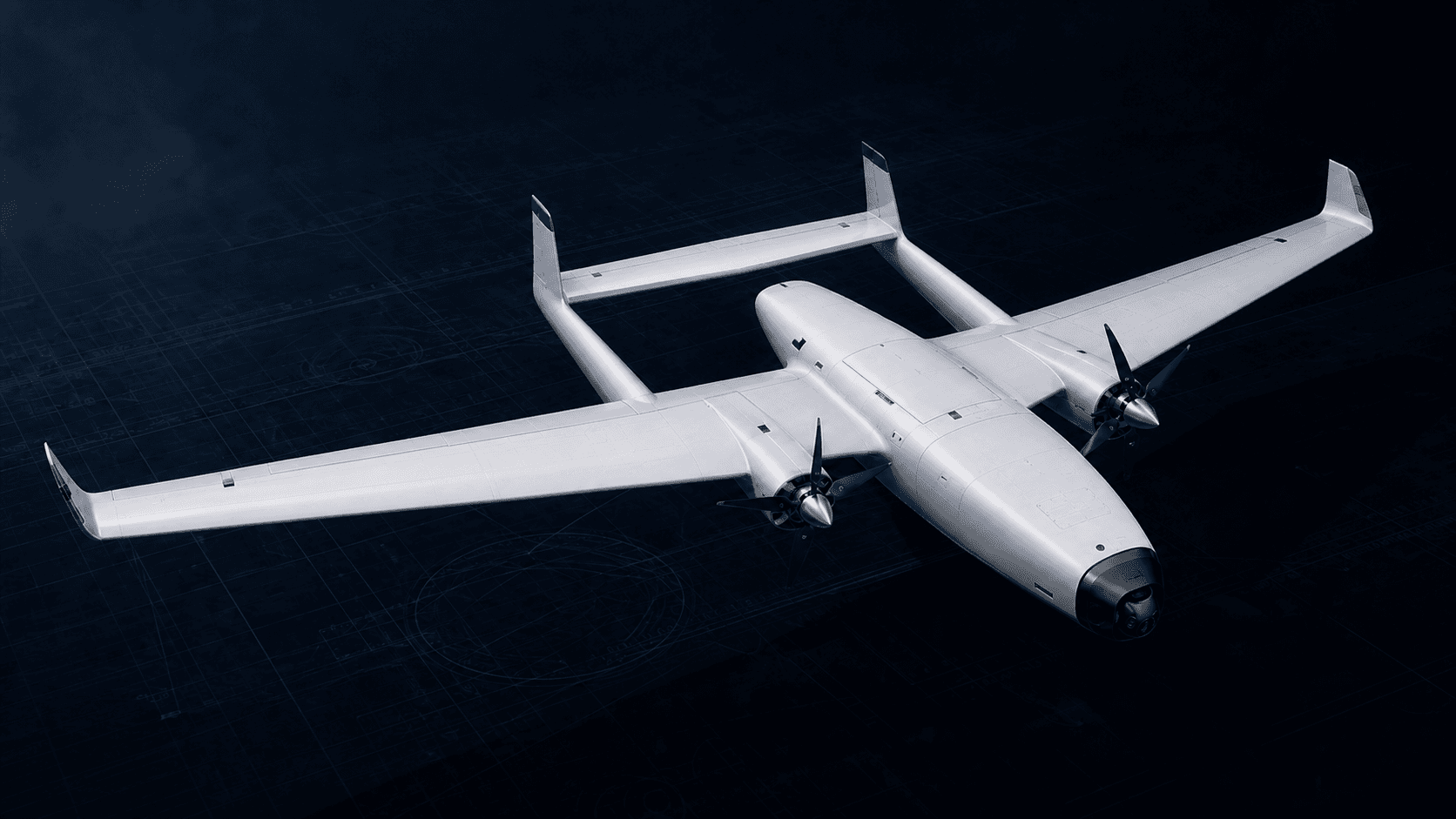
ARES Air Vehicle
CONCEPTUAL CONFIGURATIONNOT YET FLIGHT VALIDATEDModularity is the performance target.
The aircraft concept prioritizes repairability, replaceable sections, cost-conscious manufacturing, and clear separation between reclaimed non-critical structure and new safety-critical systems.
- DESIGN TARGET / 01
- Modular fuselage
- DESIGN TARGET / 02
- Swappable payload bay
- DESIGN TARGET / 03
- Low-cost repair model
- DESIGN TARGET / 04
- Mapping-oriented mission profile
05 · GROUND SYSTEMS
Field-ready in principle. Hardware validation ahead.
The ground system is being developed around independent control safety, portable telemetry, and a future directional tracking link.
GROUND STATION
IN DEVELOPMENTLaptop, telemetry modem, omni-directional backup antenna, directional antenna, portable power, and optional controller input.
SAFETY SEPARATION
Flight-critical RC control remains independent from the laptop-based ground station.
06 · ANTENNA TRACKER
Telemetry into line of sight.
PLANNED HARDWARE
SOFTWARE ARCHITECTURE IN DEVELOPMENT
SIMULATED TRACKER DATATRACKER STATE · SIMULATION
- TARGET BEARING
- 127.4°
- TARGET ELEVATION
- 16.8°
- POSITION ERROR
- 0.5°
- GPS AGE
- 0.2 s
07 · MATERIAL PRINCIPLE
Reclaimed structure. New critical systems.
Sustainability here is a classification problem—not a marketing claim. Reuse is governed by consequence and validation.
New or validated components only.
Flight controller · Power module · GPS · Receiver · Battery · ESC · Primary servos · Critical structural members
Reused only after testing.
Camera · Tracker motors · Display hardware · Non-flight computing
Suitable for reclaimed materials.
Enclosures · Tripod · Covers · Brackets · Ground-station panels · Cable routing
08 · DEVELOPMENT PATH
Progress, without invented milestones.
Concept definition
COMPLETEDARES-01 software architecture
COMPLETEDSITL and MAVLink integration
SIMULATEDTelemetry, replay, and diagnostics
COMPLETEDInitial stable Windows release
COMPLETEDRev A schematic closure
COMPLETEDRev A PCB placement complete
COMPLETEDARES Flight Computer human mechanical review
IN DEVELOPMENTControlled PCB routing
PLANNED09 · FIELD NOTES
Development log
Architecture decisions, safety boundaries, experiments, and the path from simulation to hardware.
July 2026 — Rev A Stage 6 PCB placement complete
All 69 populated components placed on the preliminary 60 × 85 mm four-layer board; routing remains blocked pending human mechanical review.
Read project noteJuly 2026 — Rev A schematic closure
69 populated components, clean ERC, exact footprint and MPN coverage, ready for placement review.
Read project noteInitial ARES-01 Desktop Release
A stable Windows-native foundation for telemetry, simulation, replay, diagnostics, and technical reporting.
Read project noteTechnical studies with visible evidence boundaries.
Read the Rev A flight-computer schematic record, SITL telemetry retrospective, airframe trade studies, and sourced disaster-response assessment.
10 · CONTINUE THE MISSION